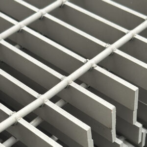
Our light-duty electroforged grating is a robust and durable product manufactured with state-of-the-art technology and high precision. It is designed to allow the passage of liquids, air, and light, making it ideal for environments that require drainage and ventilation. Available in sizes up to 3.9 × 29.5 ft, these gratings are ideal for industrial flooring, offshore platforms, mining, and more, thanks to their strength and durability. We offer various sizes, thicknesses, surfaces, and high-quality finishes in compliance with the ANSI NAAMM MBG-531-17 carbon steel standard.
The light-duty electroforged grating is designed to withstand lighter loads compared to gratings intended for heavy traffic. These gratings are typically used in areas with lower vehicular circulation, such as pedestrian zones, corridors, residential or commercial areas with light vehicle traffic.
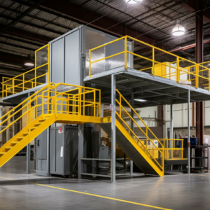
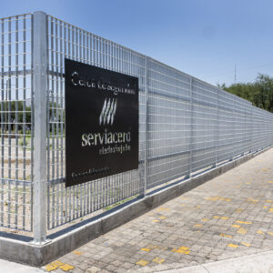
Light-duty electroforged gratings are commonly used in: sidewalks and pedestrian walkways, commercial areas with mainly pedestrian or cart traffic, platforms and building access áreas, corridors and traffic zones in industrial facilities or warehouses, residential áreas, recreational areas and parks, sports facilities, landscaping applications such as gardens or outdoor spaces, areas with light vehicles such as bicycles or motorcycles.
The light-duty electroforged grating provides numerous advantages thanks to its design for lighter loads, including: lightweight structure, allowing easy handling, installation, and maintenance, pedestrian safety, with a secure, anti-slip surface, versatility, suitable for a wide range of environments, easy installation and low maintenance, as it endures less wear, aesthetic and design flexibility, adaptable to specific projects, cost-efficiency, corrosion resistance, particularly with special surface finishes, compliance with international quality standards.
We manufacture safe and durable electroforged gratings with a strong, high-resistance structure made using cutting-edge technology. Our process ensures a perfect fusion between the bearing bars and the cross bars through controlled pressure and electric arcs during electroforging. Panels are produced in standard sizes of 2×20,2×24, 3×20 and 3 x 24 ft, with the capacity to manufacture larger panels up to 3.9 × 29.5 ft thanks to our machine’s bed size. Our light-duty electroforged gratings are engineered to allow the passage of liquids, air, and light, making them ideal for use in environments requiring drainage or ventilation. Common applications include industrial flooring, offshore platforms, industrial maintenance, mining, livestock facilities, boilers, walkways, and more—valued for their strength and durability.
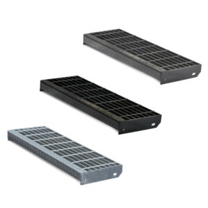
They can be manufactured in different dimensions according to customer requirements, with two surface options: Smooth surface: allows easier cleaning, greater walking comfort, prevents residue buildup, reduces footwear wear, provides an elegant and minimalist aesthetic, helps prevent injuries, and adapts to diverse uses. Serrated surface: offers higher slip resistance, increased safety, improved drainage, greater wear resistance, versatility, and prevents residue accumulation.
Available in three different finishes: bare finish, provides a minimalist, authentic appearance with low maintenance; the painted finish, which offers customized aesthetics and additional corrosion protection and the galvanized finish, that provides superior corrosion protection, increased durability, and minimal maintenance. All gratings are manufactured in accordance with ANSI NAAMM MBG-531-17, in carbon steel.
| Light traffic electroforged grating | |||||||||||||||||
|---|---|---|---|---|---|---|---|---|---|---|---|---|---|---|---|---|---|
| Allowable Loads Table | |||||||||||||||||
| Bearing bar | Span in inches | ||||||||||||||||
| 24 | 30 | 36 | 42 | 48 | 54 | ||||||||||||
| 3/4 X 1/8 | 42 | U | 355 | 227 | 158 | 116 | 89 | 70 | Note: The carrying capacity of a piece of grating subjected to a | ||||||||
| -4 | Du | 0.099 | 0.155 | 0.223 | 0.304 | 0.397 | 0.503 | concentrated load over only a portion of its width is determined by the | |||||||||
| C | 355 | 284 | 237 | 203 | 178 | 158 | stiffness of both the bearing bars and the cross bars, and therefore differs with the type of grating used. To determine the carrying capacity of gratings to such loadings, the manufacturer´s engineering should be consulted | ||||||||||
| Dc | 0.079 | 0.124 | 0.179 | 0.243 | 0.318 | 0.402 | |||||||||||
| 3/4 X 3/16 | 46 | U | 533 | 341 | 237 | 174 | 133 | 105 | |||||||||
| -6 | Du | 0.099 | 0.155 | 0.223 | 0.304 | 0.397 | 0.503 | ||||||||||
| C | 533 | 426 | 355 | 305 | 266 | 237 | |||||||||||
| Dc | 0.079 | 0.124 | 0.179 | 0.243 | 0.318 | 0.402 | 60 | 66 | 72 | Conversion Factors: | |||||||
| 1 X 1/8 | 51 | U | 632 | 404 | 281 | 206 | 158 | 125 | 101 | 84 | 70 | For gratings with other than 1-3/16" bearing bar | |||||
| -6 | Du | 0.074 | 0.116 | 0.168 | 0.228 | 0.298 | 0.377 | 0.456 | 0.563 | 0.67 | spacing, or for different desing stresses, | ||||||
| C | 632 | 505 | 421 | 361 | 316 | 281 | 253 | 230 | 211 | proportionate conversion factors apply. Refer to the | |||||||
| Dc | 0.06 | 0.093 | 0.134 | 0.182 | 0.238 | 0.302 | 0.372 | 0.451 | 0.536 | Metal Bar Grating Enngineering Desing Manual for | |||||||
| 1 X 3/16 | 57 | U | 947 | 606 | 421 | 309 | 237 | 187 | 152 | 125 | 105 | the development of such factors. | |||||
| -8 | Du | 0.074 | 0.116 | 0.168 | 0.228 | 0.298 | 0.377 | 0.466 | 0.563 | 0.67 | |||||||
| C | 947 | 758 | 632 | 541 | 474 | 421 | 379 | 344 | 316 | ||||||||
| Dc | 0.06 | 0.093 | 0.134 | 0.182 | 0.238 | 0.302 | 0.372 | 0.451 | 0.536 | 78 | 84 | Note: 1/4" is considered | |||||
| 1 1/4 X 1/8 | 61 | U | 987 | 632 | 439 | 322 | 247 | 195 | 158 | 130 | 110 | 93 | 81 | the maximum deflection | |||
| -7 | Du | 0.06 | 0.093 | 0.134 | 0.182 | 0.238 | 0.302 | 0.372 | 0.451 | 0.536 | 0.629 | 0.73 | consistent with pedestrian | ||||
| C | 987 | 789 | 658 | 564 | 493 | 493 | 395 | 329 | 329 | 304 | 282 | comfort, but can be | |||||
| Dc | 0.048 | 0.074 | 0.107 | 0.146 | 0.191 | 0.241 | 0.298 | 0.36 | 0.429 | 0.504 | 0.584 | exceeded for other loading | |||||
| 1 1/4 X 3/16 | 67 | U | 1480 | 947 | 658 | 483 | 370 | 292 | 237 | 196 | 164 | 140 | 121 | conditions at the discretion | |||
| -9 | Du | 0.06 | 0.093 | 0.134 | 0.182 | 0.238 | 0.302 | 0.372 | 0.451 | 0.536 | 0.629 | 0.73 | of the engineer. | ||||
| C | 1480 | 1184 | 987 | 846 | 740 | 658 | 592 | 538 | 493 | 455 | 423 | ||||||
| Dc | 0.048 | 0.074 | 0.107 | 0.146 | 0.191 | 0.241 | 0.298 | 0.36 | 0.429 | 0.504 | 0.584 | 90 | 96 | 102 | 108 | ||
| 1 1/2 X 1/8 | 70 | U | 1421 | 909 | 632 | 464 | 355 | 281 | 227 | 188 | 158 | 135 | 116 | 101 | 89 | 79 | 70 |
| -8 | Du | 0.05 | 0.078 | 0.112 | 0.152 | 0.199 | 0.251 | 0.31 | 0.376 | 0.447 | 0.524 | 0.605 | 0.698 | 0.794 | 0.897 | 1,006 | |
| C | 1421 | 1137 | 947 | 812 | 711 | 632 | 568 | 517 | 474 | 437 | 406 | 379 | 355 | 334 | 316 | ||
| Dc | 0.04 | 0.062 | 0.089 | 0.122 | 0.159 | 0.201 | 0.248 | 0.3 | 0.358 | 0.42 | 0.487 | 0.559 | 0.636 | 0.718 | 0.804 | ||
| 1 1/2 X 3/16 | 77 | U | 2132 | 1364 | 947 | 696 | 533 | 421 | 341 | 282 | 237 | 202 | 174 | 152 | 133 | 118 | 105 |
| -11 | Du | 0.05 | 0.078 | 0.112 | 0.152 | 0.199 | 0.251 | 0.31 | 0.376 | 0.477 | 0.524 | 0.608 | 0.698 | 0.794 | 0.897 | 1,006 | |
| C | 2132 | 1705 | 1421 | 1218 | 1066 | 947 | 853 | 775 | 711 | 656 | 609 | 568 | 533 | 502 | 474 | ||
| Dc | 0.04 | 0.062 | 0.089 | 0.122 | 0.159 | 0.201 | 0.248 | 0.3 | 0.358 | 0.42 | 0.487 | 0.559 | 0.636 | 0.718 | 0.804 | ||
| 1 3/4 X 3/16 | 87 | U | 2901 | 1857 | 1289 | 947 | 725 | 573 | 464 | 384 | 322 | 275 | 237 | 206 | 181 | 161 | 143 |
| -13 | Du | 0.043 | 0.067 | 0.096 | 0.13 | 0.17 | 0.215 | 0.266 | 0.322 | 0.383 | 0.45 | 0.521 | 0.599 | 0.681 | 0.769 | 0.862 | |
| C | 2901 | 2321 | 1934 | 1658 | 1451 | 1289 | 1161 | 1055 | 967 | 893 | 829 | 774 | 725 | 683 | 645 | ||
| Dc | 0.034 | 0.053 | 0.077 | 0.104 | 0.136 | 0.172 | 0.213 | 0.257 | 0.306 | 0.36 | 0.417 | 0.479 | 0.545 | 0.615 | 0.689 | ||
| 2 X 3/16 | 96 | U | 3789 | 2425 | 1684 | 1237 | 947 | 749 | 606 | 501 | 421 | 359 | 309 | 269 | 237 | 210 | 187 |
| -13 | Du | 0.037 | 0.058 | 0.084 | 0.114 | 0.149 | 0.189 | 0.233 | 0.282 | 0.335 | 0.393 | 0.456 | 0.524 | 0.596 | 0.673 | 0.754 | |
| C | 3789 | 3032 | 2526 | 2165 | 1895 | 1684 | 1516 | 1378 | 1263 | 1166 | 1083 | 1011 | 947 | 892 | 842 | ||
| Dc | 0.03 | 0.047 | 0.067 | 0.091 | 0.199 | 0.151 | 0.186 | 0.225 | 0.268 | 0.315 | 0.365 | 0.419 | 0.477 | 0.538 | 0.603 | ||
| 2 1/4 X 3/16 | 105 | U | 4796 | 3069 | 2132 | 1566 | 1199 | 947 | 767 | 634 | 533 | 454 | 392 | 341 | 300 | 266 | 237 |
| -16 | Du | 0.033 | 0.052 | 0.074 | 0.101 | 0.132 | 0.168 | 0.207 | 0.25 | 0.298 | 0.35 | 0.406 | 0.466 | 0.53 | 0.598 | 0.67 | |
| C | 4796 | 3837 | 3197 | 2741 | 2398 | 2132 | 1918 | 1744 | 1599 | 1476 | 1370 | 1279 | 1199 | 1128 | 1066 | ||
| Dc | 0.026 | 0.041 | 0.06 | 0.081 | 0.106 | 0.134 | 0.166 | 0.2 | 0.238 | 0.28 | 0.324 | 0.372 | 0.424 | 0.478 | 0.536 | ||
| 2 1/2 X 3/16 | 113 | U | 5921 | 3789 | 2632 | 1933 | 1480 | 1170 | 947 | 783 | 658 | 561 | 483 | 421 | 370 | 328 | 292 |
| -18 | Du | 0.03 | 0.047 | 0.067 | 0.091 | 0.119 | 0.151 | 0.186 | 0.225 | 0.268 | 0.315 | 0.365 | 0.419 | 0.477 | 0.538 | 0.603 | |
| C | 5921 | 4737 | 3947 | 3383 | 2961 | 2632 | 2368 | 2153 | 1974 | 1822 | 1692 | 1579 | 1480 | 1393 | 1316 | ||
| Dc | 0.024 | 0.037 | 0.054 | 0.073 | 0.095 | 0.121 | 0.149 | 0.18 | 0.215 | 0.252 | 0.292 | 0.335 | 0.381 | 0.431 | 0.483 | ||
U: Permissible uniform load (in kg / m2).
C: Permissible concentrated load (in kg / m)
Du: Deflection with uniform load (mm)
Dc: Deflection with concentrated load (mm)
| Theoretical Weight Chart | |||||||||||
|---|---|---|---|---|---|---|---|---|---|---|---|
| CARBON STEEL | |||||||||||
| PRODUCT | W11-2 | W11-4 | W13-2 | W13-4 | W15-2 | W15-4 | W16-2 | W16-4 | W19-2 | W19-4 | |
| BEARING BAR SPACING | 11/16" | 11/16" | 13/16" | 13/16" | 15/16" | 15/16" | 16/16" | 16/16" | 19/16" | 19/16" | |
| THICKNESS (in) | WIDTH (in) | Lbs/ft² | Lbs/ft² | Lbs/ft² | Lbs/ft² | Lbs/ft² | Lbs/ft² | Lbs/ft² | Lbs/ft² | Lbs/ft² | Lbs/ft² |
| 1/8 | 3/4 | 6.7 | 6.17 | 5.82 | 5.29 | 5.25 | 4.72 | 5.16 | 4.62 | 4.37 | 3.84 |
| 1 | 8.58 | 8.05 | 7.41 | 6.88 | 6.64 | 6.11 | 6.52 | 5.98 | 5.47 | 4.94 | |
| 1 1/4 | 10.46 | 9.93 | 9 | 8.47 | 8.04 | 7.5 | 7.68 | 7.35 | 6.57 | 6.04 | |
| 1 1/2 | 12.34 | 11.81 | 10.59 | 10.06 | 9.43 | 8.9 | 9.25 | 8.71 | 7.68 | 7.14 | |
| 3/16 | 3-Apr | 9.52 | 8.99 | 8.21 | 7.68 | 7.34 | 6.81 | 7.2 | 6.67 | 6.02 | 5.49 |
| 1 | 12.34 | 11.81 | 10.59 | 10.06 | 9.43 | 8.9 | 9.25 | 8.71 | 7.68 | 7.14 | |
| 1 1/4 | 15.16 | 14.63 | 12.97 | 12.44 | 11.52 | 10.99 | 11.29 | 10.75 | 9.33 | 8.8 | |
| 1 1/2 | 17.98 | 17.45 | 15.35 | 14.82 | 13.61 | 13.08 | 13.33 | 12.79 | 10.98 | 10.45 | |
| 1 3/4 | 21.07 | 20.4 | 18 | 17.34 | 15.97 | 15.3 | 15.64 | 14.97 | 12.9 | 12.24 | |
| 2 | 23.89 | 23.22 | 20.38 | 19.72 | 18.06 | 17.39 | 17.68 | 17.01 | 14.55 | 13.89 | |
| 2 1/4 | 26.71 | 26.04 | 22.76 | 22.1 | 20.15 | 19.48 | 19.72 | 19.05 | 16.21 | 15.54 | |
| 2 1/2 | 29.53 | 28.86 | 25.15 | 24.49 | 22.24 | 21.57 | 21.77 | 21.09 | 17.86 | 17.2 | |
To determine the table of allowable loads for the remaining models, multiply by the following factors
| TYPES OF BEARING BAR | W11-50 | W11-100 | W13-50 | W13-100 | W15-50 | W15-100 | W16-50 | W16-100 | W19-50 | W19-100 | |
|---|---|---|---|---|---|---|---|---|---|---|---|
| FACTORS | 1.5 | 1.5 | 1.44 | 1.44 | 1.24 | 1.24 | 1.23 | 1.23 | Standard | ||